-
 FAST SHIPPING
-
 COMPETITIVE PRICE
-
 EXCELLENT AFTER-SERVICE
COMPETITIVE PRICE
EXCELLENT AFTER-SERVICE
Deye Inverter F55 (DC-Volt High-Fault) Practical Analysis - Rapid Troubleshooting and Remediation of DC Overvoltage from a Real Case
Overview
F55 (DC-Volt High Fault) is a DC-side high-voltage protection fault code on Deye hybrid inverters. It is commonly caused by system configuration and operating-condition mismatches rather than hardware failure. When triggered, the inverter immediately cuts off PV input and stops PV generation. This article dissects the core causes and trigger logic of F55 using three real on-site screenshots, and provides a standardized, field‑ready procedure from data tracing to on-site remediation. The guidance is applicable to the full range of Deye residential single phase and three phase low voltage hybrid inverters and is intended for PV installers and O&M personnel.
1.Case Fault Phenomenon - Locking the Core Anomaly from Three Screenshots
In this case the residential PV+storage system repeatedly stopped exporting during daytime high‑irradiance periods. Remote monitoring raised alarms. The three on-site screenshots form a complete evidence chain and clearly show the core issue:
Figure 1 - Power Flow Screenshot
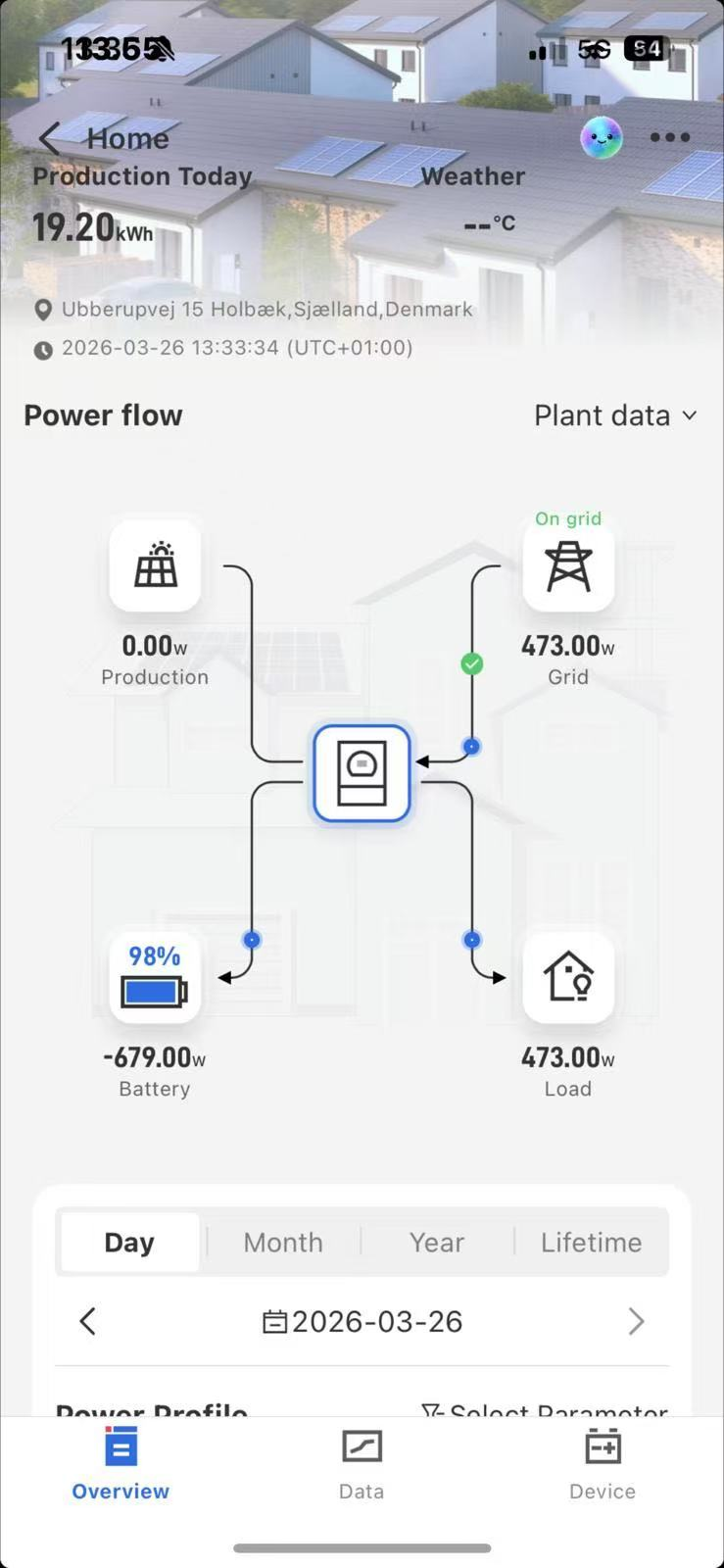
The PV generation power drops directly to 0 W. The system stops PV generation and relies entirely on
grid supply plus battery discharge to serve the load. This is the customer-perceived symptom of “no generation.”
Figure 2 - F55 Alarm Log Screenshot
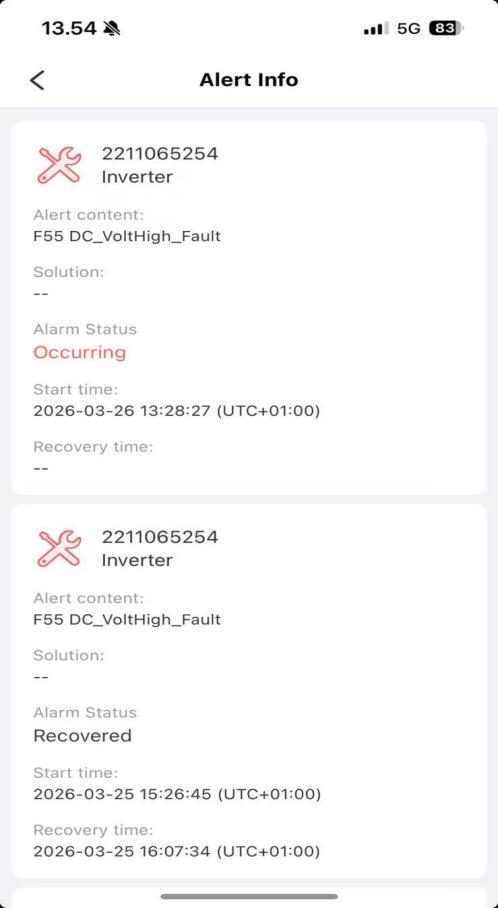
The platform reports F55 DC-Volt High-Fault indicating DC bus over voltage. Faults occur during daytime high-irradiance periods and automatically clear when irradiance falls. The repeated pattern matches typical DC overvoltage timing.
Figure 3 - Operational Data Screenshot
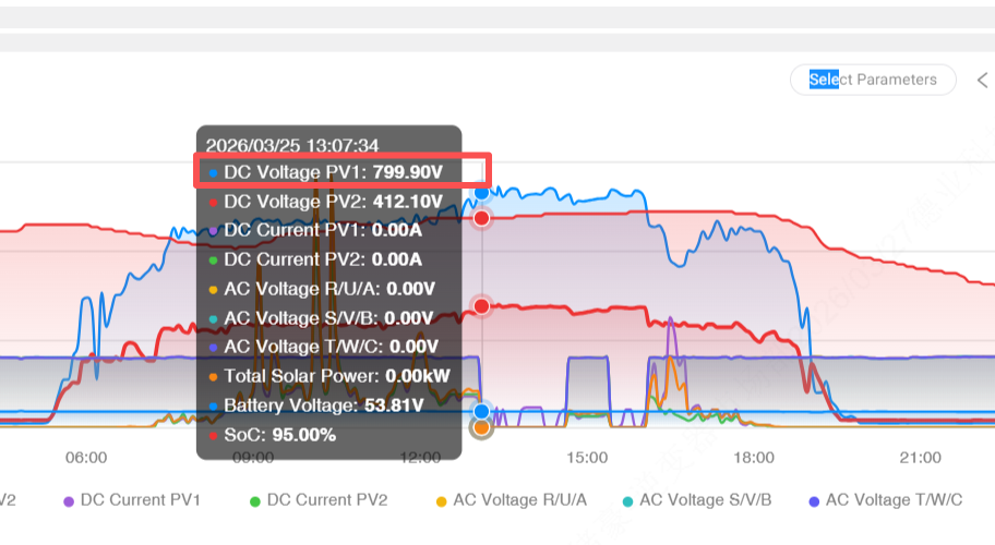
This screenshot is key to root-cause identification. The core anomalies are clear: PV1 DC voltage spikes to 799.90 V, PV1 and PV2 PV currents are 0.00 A, battery SOC is 95% with battery voltage 53.81 V, and AC side voltages are all 0 V indicating the inverter has disconnected from the grid.
The three screenshots point to the conclusion that excessive DC-side voltage triggered the inverter's protective action and caused the generation shutdown. A nearly full battery further aggravated the voltage condition.
2.F55 Fault Core Definition and Case Trigger Logic
F55 denotes DC bus overvoltage protection. The inverter's protection logic prevents high DC voltage from damaging IGBTs, DC link capacitors, the battery BMS, and other critical components. When DC voltage exceeds the configured protection threshold, the inverter executes protective actions.
Combining the three screenshots with the inverter protection behavior, the fault chain is as follows and represents a typical F55 scenario:
-Root cause: PV1 string contains too many modules in series so that the open‑circuit voltage significantly exceeds the inverter's MPPT or DC input limits. The screenshot shows 799.90 V which far exceeds typical safe limits.
-Direct trigger: At midday under strong irradiance, PV voltage rises further and crosses the protection threshold.
-Amplifying factor: Battery SOC at 95% is near full, leaving little capacity to absorb excess PV power. Excess energy accumulates on the DC side and pushes voltage higher.
-Protection action: The inverter triggers F55, cuts off PV input so PV currents drop to zero, and disconnects from the grid so AC voltages read zero. PV power falls to 0 W and the system stops exporting.
-Automatic recovery: As irradiance decreases in the evening, PV voltage falls back into the safe range, the protection clears, and the inverter resumes normal operation.
3.Core Causes of F55 (Majority Non‑Hardware Issues)
Based on the screenshots and field statistics, most F55 faults are not caused by hardware defects. This case matches two primary causes that should be the focus of on‑site checks:
This case is typical: PV1 string series count is too high so the open‑circuit voltage reaches 799.90 V, far exceeding the inverter's allowable input. Under strong irradiance, overvoltage protection is inevitably triggered. Some cases also show imbalance between PV1 and PV2 in module type or string count, causing one string to exceed safe voltage.
High battery SOC above 85% is not the root cause but acts as a voltage amplifier. With the battery nearly full, charging power drops and excess PV energy cannot be absorbed. If anti‑islanding or anti‑reverse settings prevent exporting to the grid, the excess energy accumulates on the DC side and accelerates F55 triggering.
Other common non-hardware causes
-Incorrect parameter settings such as overly strict anti‑reverse limits, disabled power smoothing, or incorrect battery charge cutoff settings that allow voltage to spike.
-DC wiring issues such as loose or oxidized connections that distort voltage sensing and cause false overvoltage detection.
4.Standardized F55 Troubleshooting Procedure-Remote First, Then On-Site
Follow the principle “remote screenshot tracing first, then on‑site practical checks; inspect circuits before hardware”. The three screenshots can identify about 90% of issues and avoid unnecessary teardown.
Step 1 - Remote screenshot tracing (core, 5 minutes to lock root cause)
Retrieve the three core screenshots from the platform and verify four points:
-From Figure 2 confirm F55 and that triggers occur during high irradiance, indicating PV - side issues.
-From Figure 3 check PV voltage and current. Voltage far above MPPT or input limits with zero current points to PV string configuration issues.
-From Figure 3 check battery SOC. High SOC above 85% indicates insufficient absorption capacity.
-From Figure 1 and Figure 3 check AC side to exclude grid issues as the cause of shutdown.
Step 2 - PV‑side on‑site checks (core remediation)
-Disconnect PV from the inverter and measure PV1/PV2 open‑circuit voltages with a multimeter to verify the screenshot readings.
-Recalculate string counts and ensure open‑circuit voltage is within safe limits under expected temperature conditions.
-Inspect PV DC terminals for loose connections or oxidation and check modules for damage or shading.
Step 3 — Battery and parameter optimization (remove amplifying factors)
-Restore battery charge cutoff and other battery parameters to manufacturer defaults.
-Avoid charging during peak irradiance hours such as 11:00–15:00 and shift charging to grid off‑peak periods to increase absorption headroom.
-Appropriately relax anti‑reverse/export limits within regulatory allowances and enable power smoothing to suppress voltage spikes.
Step 4 — Hardware checks (only if prior steps fail, rare)
-Update inverter firmware and, if necessary, restore factory settings and reconfigure parameters.
-Contact Deye technical support for inspection of DC voltage sensors, IGBTs, and the battery BMS. Do not disassemble the inverter without authorization.
5.Case‑Specific Remediation Plan — Practical and Durable
Focus on PV string correction and battery/parameter optimization. All actions below are field‑executable and should eliminate recurrence.
-For the PV1 voltage reading of 799.90 V, immediately reduce PV1 string series count so open‑circuit voltage falls within the inverter's allowable input range with a safety margin. After reconfiguration, measure open‑circuit voltage in the disconnected state and only reconnect when readings are normal.
-Ensure PV1 and PV2 use identical module types, string counts, and preferably the same production batches. Keep inter‑string voltage differences minimal.
-Set battery charge upper limit to a level that leaves headroom for PV absorption, for example 80%–85% SOC.
-Allow limited export to the grid where permitted to avoid DC energy accumulation.
-Enable power smoothing and PV power limiting features to suppress sudden voltage or power surges.
-Tighten DC terminals on PV and battery sides, remove oxidation, and ensure proper insulation.
-Monthly retrieve the three core screenshots to monitor PV voltage and battery SOC and intervene early if anomalies appear.
7.Key Takeaways
-F55 is a normal safety protection action and does not necessarily indicate hardware failure. Most occurrences are caused by PV string configuration exceeding inverter limits. Battery high SOC and improper parameter settings are common amplifying factors.
-Rapid diagnosis relies on three screenshots: power flow, alarm log, and operational data. These images enable a five‑minute root‑cause trace in most cases.
-Remediation priorities: correct PV string configuration to eliminate the root cause, and optimize battery and inverter parameters to remove amplifying conditions and prevent recurrence.
Actionable checklist
-Retrieve and save Figure 1, Figure 2, and Figure 3 for each incident.
-Disconnect and measure PV Voc in the field.
-Recalculate and adjust string counts to meet inverter input limits.
-Coordinate battery charge limits with the battery vendor and enable power smoothing.
-Document changes and monitor monthly via remote screenshots.
←
Deye SE-F Series Low-Voltage Batteries: What Changes Across the Range - and What It Means for Upgrades
→
F33 Is Not Always a "False Alarm": Why Phase Current, AC Coupling and Transient Loads Matter
 +31610999937
 [email protected]
 De Werf 11, 2544 EH The Hague, The Nederland.WhatsApp: +1 (917) 257 2995/
Copyright © 2023 Uni Z International B.V. VAT: NL864303440B01 All Rights Reserved
 Solar Energy Storage System Solutions and Products

 0
0


 italiano
 Polskie
 Nederlands
 Deutsch
 Français
 Español
 Український
 Lithium Battery 100AH, 6.1KWh, IP21")


